● About 3D-EM wave analysis by FEM...

Objective of 3D-EM analysis is tiny twin hole on metallic thin film illuminated by laser light. These few hundreds of nm holes transfer light wave as free electron oscillation and create few tens of nm bright spot at rear surface of film. This fantastic structure will be applied to, for example, apex of fiber probe for scanning near-field microscope (SNOM).
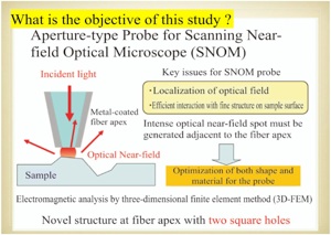
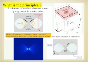

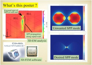
Inside or between twin hole, laser light is converted to number density modulation of free electron in metal, and the modulation wave called surface plasmon polariton (SPP) propagates along sharp edge inside twin hole. SPP waves couples at rear surface of metallic film and create few tens of nm bright spot on the film surface.
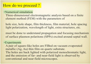
This study has been focused on SPP propagation and creation of bright spot around twin hole structure by numerical simulation based on 3D-FEM. In the experiment, the actual structure has been fabricated by focused ion beam (FIB). Collaboration between the simulation and experiment will give us sophisticated ideal structure of twin hole to create smallest and brightest spot.
Left figure shows complex refractive index of silver thin film. The imaginary part (red curve) is large through visible region. This means that imaginary part of complex dielectric constant is negatively and its absolute value is large. Therefore strong inverse polarization or inverse electric field will be excited by elextric field of light. Such polarization causes SPP waves.
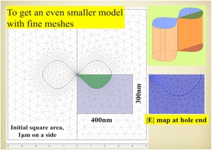
3D-FEM simulation process needs segmentalization of solid model as shown in left figure. Standard element shape is tetrahedral. Huge number of simultaneous equations based on Maxwell's equations will be constructed at whole nodes in the model. The resultant sparse matrix will be solved by direct solvers or iterative solvers, and 3D-EM distribution in the model will be finally found.
After simulation by Xeon (8 core) computer, localization, propagation, and enhancement of SPP wave has been observed around dividing wall between the two holes. Entire region of hole is a kind of waveguide because it could have propagation mode as shown in top left inlet in left figure. But such mode is not dominant because of its large attenuation constant. Mode as shown in bottom left inlet has small attenuation constant.
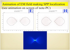
The dominant mode for SPP propagation has electric- and magnetic- field as shown in left figure. This mode will be excited efficiently by electric field of light which is perpendicular to alignment of twin hole. That is to say, polarization of light is perpendicular to alignment of the holes.
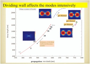
Propagation mode analysis based on 2D-FEM has given us four major modes as shown in left figure. But only bottom left mode is dominant in twin hole structure fortunately. And the propagation wavelength decay length are strongly depend on thickness of dividing wall because they may be affected by interaction between each SPP wave in the holes.
COMSOL Multiphysics and RF module are trademarks or registered trademarks of COMSOL AB in Sweden.
